BASIC RONCHI INTERPRETATION
Only treats concave
mirrors Roncigrams.
Be aware that refractive surfaces, systems in autocollimation etc.
may have the Ronchi pattern reversed.
GOTO RONCHI INDEX
Copyright – P. J.
Smith
But permission is
given to distribute this material in unaltered form as long as it is not sold
for profit.
A Ronchigram by itself
is useless.
We must also know
1.
Grating
frequency – eg. 4 line pairs per mm.
2.
F:NO
of the test beam passing through the grating.
This is usually twice the F:NO of the surface if it is to be used like a
Paraboloid in a telescope. Usually this
is defined when users specify the mirror diameter and radius of curvature and
no more details are required. There are
more details in the program Ronchi Estimates and Advanced tests.
3.
Whether
inside or outside the centre of curvature.
4.
Whether
refractive or reflective surfaces, single pass or double pass path etc.. This will not be considered further here –
see under advanced tests.
If 1 2, and 3 are known, it
is unnecessary to measure the exact position of the grating as this defocus
information is now fully defined by the Ronchigram. Because the eye finds it difficult to judge subtle Ronchi band
shape during aspherizing, some do measure this defocus distance as a cross
check
During rough figuring, we
want a quick method to indicate the shape of a surface with respect to a
sphere.
If the final target is a
sphere, this method may be continued through final figuring, but if we aim for
a Paraboloid, a change of tactics is needed.
Most Paraboloids are figured after obtaining an excellent sphere, so, no
matter what type of surface we aim for, the ability to test with respect to a
sphere is paramount. No measuring rig
is needed for this and the Ronchi test is a simple solution.
As previously stated, the most basic prerequisite is
knowing if the grid is inside or outside the
Centre of Curvature of the surface.
In practice, it is easy to
move the grid towards the mirror until more and more narrower lines are
seen. The Ronchi grid is now inside the
Centre of Curvature as in the diagram above. An experienced mirror tester simply
moves the grating either well inside (closer to mirror) or well outside
(further from mirror) and then finds which way it must be moved to decrease the
number of bands.
So, if by moving the grating back, the
number of bands decreases, you are inside the centre of curvature.
Near the
crossover point, the Ronchi pattern will become coarser and disappear into a
blur. When you know how, this position
can give a lot of information in the same way as a Foucalt test. But, since this is primarily about
interpreting the Ronchi bands, we will ignore this situation.
For sensitive work, you
must move the grating so only a few bands are visible. Very seldom will you
want more than 8 bands over the mirror and often you will want only four,
three, two, or even less for critical work.
Many of the following simulations show more bands to help illustrate
band shape but in practice you will use less for precise work.
There is no reason the
outside region may not be used, but for consistency, only one set is considered
here. Results for the other region are
simply assessed in the opposite sense.
Sometimes, outside testing
may be advantageous. Often clearer
bands are visible just outside rather than inside. When examining an aspheric surface, choosing different positions
increases sensitivity on certain parts of the surface. For example, when examining a deep
Paraboloid, the inside position is best for central surface detail, the outside
for edge detail.
I have chosen to consider
the inside as opposed to the outside Grating position because this results in
far more eyerelief when working with small deep mirrors. Non-glasses wearers may think this a trivial
reason – others will disagree.
Examination of these
diagrams will show how the forward position of the Ronchi Grating allows a
wider cone of light to converge on the pupil.
Spectacle wearers would
have no difficulty working in the rear area with an F:8 mirror. Because normal concave mirror testing is
usually performed at the centre of curvature rather than the principal focus,
the ray cone is actually working at F:16 during the test. If you are testing a very fast mirror, it
may be mandatory to work exclusively in the forward region.
Certain features are more
visible when working in the outside region, but it is more a matter of knowing
what to look for. Here we are more
interested in a consistent, easily remembered, system, and I have chosen the
forward region.
Simple, easily
remembered system best.
It is tempting to initially
approach the interpretation of Ronchigrams by analysing offsets, zonal
curvature etc. but a better first step is simply to learn a handful of key
patterns. We were initially taught our
alphabet by rote. Later this was built
on for more complex operations.
Luckily, we do not need to learn many basic patterns to be very
useful. Later, we can extend this by
more detailed analysis.
Remember, that we did not
need to relearn our multiplication tables to handle negative numbers. A consistent, simply applied inversion
protocol, takes care of the problem.
Similarly, once we learn a
few basic Ronchi patterns, by noting grating position and whether a refractive
or reflective surface, we then deduce profile by applying the correct number of
inversions. Finally, we may extend the
test by analysing less usual patterns.
Finally, beware of one system often mentioned to interpret Ronchigrams
assuming the bands present some sort of contour map of the surface. This is incorrect in theory because the bands
represent slope, not profile and this can be misleading in practice because the
slope information must be integrated and the result is not intuitive.
If you assume the bands
represent a contour, the inside of a mirror surface does bear some relation to
the correct results. Edge results,
especially, may be quite wrong.
The best advice I can give a newcomer is to learn off by heart about
five common patterns so you never make any gross errors when assessing surface
profile. Then interpret variations from
these main patterns. By limiting
ourselves to the inside Ronchigrams, there is far less chance for memory lapses
and confusion.
The Sphere
A Sphere gives
straight, evenly spaced Ronchi Bands
No matter where the grating
is positioned, a reflective Sphere will result in straight, evenly spaced
Ronchi bands when examined at the Centre of Curvature because the resulting
Wavefront is Spherical. The spacing is
a measure of the defocus from the Centre of Curvature. The Sphere on the right has its Centre of
Curvature closer to the grating than has the left Ronchigram.
It does not matter if a
dark or light band is in the centre, or there is an even or odd number of
bands, or even if the bands are displaced sideways, this always holds true.
It is possible for a
complex optical instrument with no Spherical surfaces to give a Spherical
Wavefront which, of course tests as a Sphere.
This is the case with any Null test which is the best possible testing
situation. Auxiliary optical reflective
and or refractive surfaces are introduced in the ray path. See under Null figuring.
A
Sphere is always our reference, so if the bands are not straight and evenly
spaced, we attempt to estimate
departure from spherical.
Sphere within a Sphere
A very common situation is
represented above. Here, the inner and
the outer portion of the concave mirror are both spherical since the lines are
straight and evenly spaced in both areas.
In this case, the inner area has its centre of curvature closer to the
grating giving wider spaced lines. If
the grating is inside, the COC inner zones have a shorter radius of curvature.
The transition area is seen
as a circular zone where the slope of the surface suddenly changes. Although surface height changes, it is the
change of slope, which directly repositions the lines rather than the
difference in height of the surface.
Note how the region of abrupt slope change corresponds with the maximum
distortion of the bands [1].
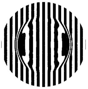
Isolated Ridge
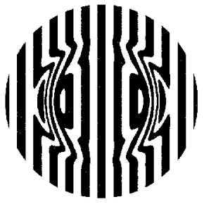
Determine how this
differs from the previous Sphere within a Sphere diagram.
At first glance, they look
the same. But on close inspection,
there are two differences.
1.
The
lines actually reverse curve instead of just kinking outwards.
2.
The spacing
of the inner and outer regions are identical.
Since the band spacing is
the same in the outer and inner regions, they represent portions of the same
sphere.
The region of band
distortion in this example represents a raised ridge.
![]()
If inside COC, if the bands kink
inwards, ie. closer together, the surface defect is a raised ridge
Turned Down Edge
Turned down edge is very
common. It should not be confused with
the incomplete polish situation covered previously. In this case, the edge becomes steeper and steeper as we move
outwards. It usually spans quite a very
small range at the very outside of the mirror.
Please note the span in this example is exaggerated for clarity.
Turned Down Edge
viewed Inside Centre of Curvature
causes Ronchi bands to
hook inward at the edges
The mirror profile is drawn with respect to a reference Sphere.
In this case the edge falls
off so drastically that the slope changes at an alarming rate. This accounts for added bands at the extreme
left and right edges. You should not
confuse the extra bands at the edges with diffraction effects seen on the
extreme left and right of the mirror.2 In this case, the edge is intolerable and
must be eliminated in some way.
The best area to diagnose this situation is the bend of the ends of
bands
departing the mirror at maybe
1/3 of the way out from the centreline.
It is better if you never use this
extreme left and right region when interpreting Ronchigrams.
Gentle Overall
Depression.
Apart from some
irregularity, the mirror depicted below indicates a depressed centre with
respect to a sphere.
ATM’s will recognise this as approaching a parabola in shape.
The shape of these lines
depends on the dimensions of the mirror and position of the grating and each
case should be examined in detail.
Fortunately, many computer simulations are now available to generate
these patterns so there is no excuse for the mirror maker to simply guess the
band shapes.
PARABOLOIDS
Each of these represents a Ronchigram of a Paraboloid.
The Grating has been moved to different positions resulting in
the same number of bands, so making comparison simpler.
This has dominated the type of optics made by ATMs and is given far more
attention under Advanced
interpretation and Aspherizing. Until you have a good sphere without a
turned edge, it is best to leave this until later.
The
inverse patterns
The situations presented so far
have been oversimplified
because a large number of
combinations are possible.
This is
because :-
- The grating may be placed
outside, as well as inside, the COC.
- Each of the surface shapes has
an inverted counterpart.
Fortunately, we do not have to learn each
pattern because
we simply invert the pattern for each of these
changes.
It is a
worthwhile exercise to prepare a simple wall chart including the inverted
patterns. There is no need for this to
be in any way fancy. A crude sketch is
perfectly adequate and will serve a better purpose than simply copying
something fancy from a book or the Internet.
My program RonchiZ will be found
useful to explore this further and
generate patterns for gratings in different positions. See software. It is, however,
not needed, because simple inversions of the
patterns are easy to generate mentally.
|
|
SPHERE |
TWIN SPHERE |
TURNED DOWN EDGE |
TURNED UP EDGE |
DEPRESSED CENTRE |
RAISED CENTRE |
|
INSIDE COC |
|
|
|
|
|
|
|
OUTSIDE COC |
|
|
|
|
|
|
GOTO RONCHI INDEX