RONCHI
Non Linear & Unequal Gratings
Applications of Non-linear and Unequal gratings.
Because some of these are odd techniques not covered in detail
elsewhere, information, such as references and more detail than just the
grating type may be given.
One should be aware that all of these may be modelled with a Raytracing
program.
GOTO RONCHI INDEX
Copyright – P. J.
Smith
But permission is given to distribute this material in unaltered form as
long as it is not sold for profit.
Equally Spaced Circular Gratings [1]
Must be used with a
Pinhole source
The grating on the
left gives a ‘Ronchigram’ as shown on the right.
The unequal spacing
indicates Spherical aberration. Of course, if the outer rings are wider the
Spherical aberration is of opposite sign.
This is typical of the amount of Spherical Aberration when testing a 4
inch F:4 parabola at centre of curvature.
A perfect sphere of
course returns evenly spaced circles.
The above are typical
patterns introduced by other pure aberrations.
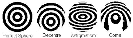
It is interesting that
Astigmatism, which does not show very well in normal Ronchi testing, shows
reasonably well. Whether it is
sensitive enough to be useful I am not sure, but this should be
investigated.
The obvious method of
manufacturing a circular grating is by the photographic process.
The Popov Grating
An Unequal Circular Grating
Popov [2]
calculated how to modify a circular grating by grading the ring spacings so,
when a parabola is under test, the resultant ‘Ronchigram’ appears as a circular
pattern of uniform spacing. The idea is
that the eye can better evaluate deviations from the even width ‘Ronchi”
pattern. Later (1977), Hopkins and Shagam pointed out that gratings like this
may be derived from raytracing spot-diagrams.
Since Raytracers are now a common facility available to ATM's this
should be of interest.
This grating must be used with a pinhole source.
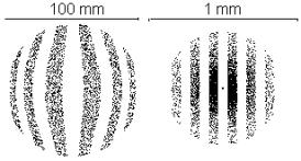
It is possible to use a Raytracing program to generate
the required pattern for the Popov Grating.
The following has been generated for a 140 mm F:3
mirror using Zemax. [3]
The grating at left if placed exactly 5 mm in front of
the paraxial test focus will produce the appearance of the mirror Ronchi image
on the right.
I have never tried this but would expect the scheme to
be useful, although far from definitive.
The most accessible resource is the small Sky and Telescope article
which does give some information on the computations required. Alternatively, use a Raytracing Program.
I have never used this
technique. A method to accurately place
the grating is obviously needed. One
could either locate the paraxial focus, moving the grating the required offset
distance, or else arrange the Ronchigram to show the exact number of
bands. I cannot recommend which is
best.
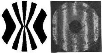
The so-called Mobsby Grating
In 1974 Malacara and Cornejo [4]
placed the Mobsby test using curved Ronchi Gratings on a correct mathematical
basis. Mobsby had previously published
information in the relatively obscure Journal of the Wessex Astronomical
Society.
But both of these were predated by an idea from J.
Pastor. [5] One wonders what it should be called, but the name ‘Mobsby’ seems to have stuck.
Later (1977), Hopkins and Shagam pointed out that
gratings like this can be derived from raytracing spot- diagrams which is now a
common facility available to ATM's.
This grating must be used with a pinhole source.
It is possible to use
a Raytracing program to generate the required pattern for the Mobsby Grating.
The following has been generated for a 4 inch F:4 mirror using Zemax. [6]
The grating at left if placed exactly at the paraxial test focus will
produce the appearance of the mirror Ronchi image on the right.
The case used above is
simply one possible example. It might be
more useful to choose fewer bands across the mirror and place the grating in a
different position. It will serve,
however, as an example of the Mobsby technique and how to harness a Raytracing
program to map the grating. From there
on a photographic technique can be used.
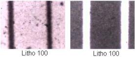
Here is a negative used to generate one such grating and the resulting
Ronchigram .
I have never used this
technique. A method to accurately place
the grating is obviously needed. One
could either locate the paraxial focus, moving the grating the required offset
distance, or else arrange the Ronchigram to show the exact number of
bands. I cannot recommend which is
best.
Other sources of
information on this test can be found on the web. See under Software.
The Ronchi Hartmann Mask
In 1990 and 1992, Cordero
et al. emphasized that the Hartmann and Ronchi tests are really only different
because of the position of the "grating" and applied a common
mathematical approach to both. [7]
This leads one to the inverse of a Mobsby test. If a full size mask corresponding to the
shape of a Mobsby Grating is placed over a mirror surface and a pinhole is
imaged at the position where a Mobsby Grating would be placed, the resultant
image will show straight lines when the surface is corrected.
This is most conveniently
performed by placing a film at the image position or using an eyepiece to view
the image. An eyepiece usually
introduces distortion and a graticule atits
focal plane would be needed to show what straight lines look like.
It is possible to use
a Raytracing program to generate the required mask for the Ronchi Hartmann
test.
The following has been generated for a 4 inch F:4 mirror using Zemax.
The left represents a mask which would give the ‘image on the right if
film is placed 3 mm in front of the paraxial test focus.
It is no surprise that this
simply represents the inverse of a Ronchi test.
In a similar way it would
be possible to invert the Circular grating test by using a mirror mask in the
form of unequal circles. I will leave
it to the reader as an exercise to use a raytracer to derive the mirror mask.
Unequal Gratings
These are
not really Non-Linear gratings but they deserve a mention somewhere.
It is easy to produce
different ratios of light and dark grating bands photographically.
This has been used to
produce narrower and more contrasty bands in Ronchigrams and was described by Murty
and Cornejo [8].
Later, DeVany wrote this up in “Applied Optics”. He shows results of different combinations
used in the Grating/Grating mode.
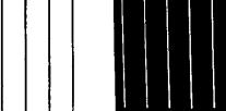
Examples
of Unequal Ronchi Gratings.
Resulting Unequal Ronchigrams are shown.
He seems to have missed the
fact that by varying the width of a slit in conjunction with a grating a large
measure of control is already available.
Equally, some control is also available by simply dissolving away some
of the metal in a woven bronze grating
in Nitric acid. It must then be used
with a slit source.
My preference is for a
grating with dark spaces somewhat narrower than the light areas but do not
consider the results from these extreme gratings above as especially
worthwhile.
GOTO RONCHI INDEX